Sekhar Chandra Ray*
Department of Physics, College of Science, Engineering and Technology, University of South Africa, Private Bag X6, Florida, 1710, South Africa
Frontier Research Today, 2018, 1:1006
Published Online: 28 December 2018 (Article)
DOI: 10.31716/frt.201801006
*Corresponding Author. Email: This email address is being protected from spambots. You need JavaScript enabled to view it. and This email address is being protected from spambots. You need JavaScript enabled to view it.
Abstract
The electronic properties, bonding structure and magnetic behaviours of oxygen- and chlorine-treated nitrogenated carbon nanotubes (N-CNTs) were studied using x-ray absorption near-edge structure (XANES), scanning photoelectron microscopy (SPEM) and PPMS measurements. The C and N K-edge XANES spectra of chlorine-treated N-CNTs consistently reveal the formation of pyridinelike N-CNTs by the observation of 1s→π*(e2u) antibonding and 1s→π*(b2g) bonding states. Features in the C K-edge XANES spectra are shifted by ~0.3 eV toward higher energies and by ~1.1 eV toward lower energies relatively to those of the more symmetrical pyridinelike and graphitelike structured N-CNTs upon chlorination and oxidation, respectively. Increases in N K-edge XANES intensities for both chlorination and oxidation reveal substitution of C–C bonds by C–N bonds consistent with the observed valence-band photoemission spectra of the decrease of the C 2s bond and the increase of the N 2s bond. The valence-band photoemission spectra obtained from SPEM images indicate that chlorination of the nanotubes enhances the C–N bonding. First-principles calculations of the partial densities of states in conjunction with C K-edge XANES data identify the presence of C–Cl bonding in chlorine treated N-CNTs. In the electron field emission of chlorination (N-CNT:Cl) and oxidation (N-CNT:O) of N-CNT shows a high current density (J) of 15.0 mA/cm2 has been achieved on chlorination, whereas low J of 0.0052 mA/cm2 is observed on oxidation compared to J = 1.3 mA/cm2 for untreated N-CNT at an applied electric field EA of ~1.9 V/mm. The turn-on electric field (ETO) was ~0.875 and 1.25 V/mm was achieved for N-CNT:Cl and N-CNT:O, respectively, with respect to ETO = 1.0 V/mm for untreated one. The magnetic behavioural changes occurs when N-CNTs are functionalized with Cl and O respectively.
Keywords
Nitrogenated carbon nanotubes, XANES, Magnetic hysteresis loop
1 Introduction
Since carbon nanotubes (CNTs) were discovered by Iijima1, they have been viewed as attractive functional fillers for producing novel composites due to their unique morphology, high mechanical strength, outstanding thermal and electrical conductivities, and capability for electron emission. These unique morphology and structure of carbon nanotubes (CNTs) keep attracting a great number of researchers to explore the novel properties of these materials. CNTs are considered as rolled-up graphene sheets, the ends of which are capped with a hemisphere of a Bucky ball structure. The exact structure of a nanotube depends on the different angles and curvatures in which a graphene sheet can be rolled into a tube and is determined by a single vector, which is called a chiral vector and discriminates CNTs into “zigzag”, “armchair”, and “chiral” forms. The electronic properties of a nanotube change in correspondence to its structure; thus, armchair nanotubes are metallic, while zigzag and chiral can be either metallic or semiconducting. In general, single walled carbon nanotubes (SWCNTs) are a mixture of metallic and semiconducting material, depending sensitively on their geometrical features, while multi-walled carbon nanotubes (MWCNTs) are regarded as metallic conductors. Especially for SWCNTs, the electronic properties vary from metallic to semiconducting depending on their structures. Additionally, as a result; of the 1-D nature of CNTs, electrons can be conducted in nanotubes without being scattered. The absence of scattering of the electrons during conduction is known as ballistic transport and allows the nanotube to conduct without dissipating energy as heat. However, as prepared CNTs possess a variety of diameters, length distribution, and structures within the same CNTs. It is also well known; that the methods of production of CNTs generate impurities such as by product carbonaceous species and residues from the transition metal catalysts used in preparing CNTs. Moreover, CNTs are insoluble in all solvents due to strong van der Waals interactions that tightly hold them together; forming bundles. All of the above decrease the overall yield of usable material and interfere with most of the desired properties of the CNTs. In this frame, CNTs can undergo chemical functionalization to enhance solubility in various solvents and to produce novel hybrid materials potentially suitable for applications. The main approaches for the functionalization of CNTs can be grouped; into two main categories: (a) the covalent attachment of chemical groups, through reactions on the conjugated skeleton of CNTs, and (b) the noncovalent supramolecular adsorption or wrapping of various functional molecules onto the tubes. The covalent functionalization of CNTs allows functional groups to be attached to tube ends or sidewalls. The sites of highest chemical reactivity in the CNTs structure are the caps, which have a semi-fullerene-like structure. Chemical functionalization of CNTs tips has been performed mainly on the basis of oxidative treatments. As a general rule the CNT oxidation yields opened tubes with oxygen-containing functional groups (predominantly carboxylic acid) at both the sidewall and the tube endings. These groups are use as chemical anchors for further derivatization. Although the bonding in CNTs is similar to that of graphene, curvature of the nanotube sidewall renders addition reactions to the cylindrical nanostructure more favorable than in a flat graphene sheet2,3. In addition, several experimental studies exist, which reveal that the hexahedral chemical reactivity increases with increasing curvature of the sidewall. This dependency has been attributed to curvature induced strain that originates from pyramidalization of the sp2 -hybridized carbon atoms and the misalignment of π-orbitals4,5. The chemical modification of carbon nanotubes (CNTs) are highly interest for changing their mechanical, electrical and electronic properties that are useful for the variety of applications ranging from nano-electronics and nanoelectromechanical systems to nanocomposites6. Among the large number of chemical modifications/treatments of CNTs; functionalization, dispersion and chemically doping with different functional groups would afford a number of opportunities for tailoring the structural and electronic properties7,8. The doping of nitrogen impurities in CNTs was found to be a possible route to tune the band gap such that CNTs can be exploited to make various electronic devices9. However, direct doping of nitrogen impurities is not the only way to control the electronic property; chemical modification and/or purification of the CNTs can also alter the electronic properties and improve the performance of various devices. The fluorinated CNTs can be tuned; from metal to semiconductor/insulator with high resistivity at elevated temperatures10. The fluorination can also improve the wetting of nanotubes in water by inducing a surface dipole layer on the nanotube wall. This effect may be useful in battery and super-capacitor applications11. Iodine- and bromine-doped CNTs were found to enhance the electronic/electrical properties by increasing the density of free charge carriers12. Therefore, it is interesting to understand the effect of chemical modification of CNTs using halogens (F, I, Br and Cl). Different workers have been investigated the fluorine-, iodine-, bromine-treated CNTs10-12 and CNTs-based nanomaterials13-15. A comprehensive study of the electronic structures and bonding properties of N-CNTs:Cl is complementary to the understanding of the properties of halogen modified CNTs. Ray et al.17 have observed from experimental results and hence theoretical calculation that chlorine bonded compounds (i.e. C-Cl C-N-Cl) formed on the surface of nitrogenated carbon nanotubes (N-CNTs) and their electronic properties are changes during the functionalization of N-CNTs in chlorine plasma atmosphere [denoted as N-CNTs:Cl].
Again, different oxidative treatments of CNTs were studied by Ago et al.8 and found the affect the density of states (DOS) of valence bands and increase the work function. Ago et al. observed that gas-phase treatment preferentially forms hydroxyl and carbonyl groups, while liquid-phase treatment forms carboxylic acid groups on the surface of CNTs. Recently, Watts et al.16 found that the conductivity of CNTs are increase/decrease on oxygen treatments that depends on dry air or humid environment. Similar enhancement of conductivity and change of Fermi level is also observed by Weglikowska et al.7 during chemical modification of CNTs using chlorine containing SOCl2 compound. In case of chlorine treatment17 using dichlorocarbene compound, the surface of CNTs are modified with presence of other functional forms of carbon (i.e C-Cl, C-O and O-C=O) on the surface of CNTs by decreasing the density of C-C bonds. However, either on oxidation or chlorination it shows not only the surface modification but also changes the structural as well as electronic properties of CNTs7-18. We have observed from experimental results and hence theoretical calculation that chlorine bonded compounds (i.e. C-Cl C-N-Cl) formed on the surface of nitrogenated carbon nanotubes (N-CNTs) and their electronic properties are changes during the functionalization of N-CNTs in chlorine plasma atmosphere [denoted as N-CNTs:Cl]11. We also observed the magnetic properties drastically changed on functionalization of CNTs with chlorine and oxygen.
In the present study, it is studied and discussed the surface morphology, microstructural properties, electronic structure, bonding properties and change of magnetic behaviors with functionalization along with theoretical calculation for supporting these results of functionalized N-CNTs in oxygen [denoted as N-CNTs:O] and chlorine functionalized N-CNTs using different measurements.
2 Experimental details
In the preparation of CNTs, the vertically oriented multi-wall N-CNTs were initially synthesized by microwave-plasma-enhanced-chemical-vapor deposition on silicon substrates pre-coated with an e-beam evaporated 7nm thin Fe catalytic layer. These N-CNTs are rigid having high density, vertically-oriented and a bamboo-bush-like structure.19 The CNTs are prepared with a CH4/H2 gas mixture exhibited a typical multiwall carbon nanotube structure; whereas the majority of the CNTs found in the CNTs prepared with N2 addition showed bamboo-like structure. Then, the obtained N-CNTs were chlorinated in an inductively plasma-coupled reactor in flowing Cl gas at 5 sccm for periods of 1 and 5 min [denoted as N-CNTs:Cl (1min) and N-CNTs:Cl (5min) later on]. During chlorination, the total pressure was 40 mTorr and the applied input power was 150W. These CNTs are denoted as N-CNTs:Cl. The oxygen treatment was performed under the air-atmospheric plasma conditions for 5 sec at a discharge power of ~ 0.5 kW using a dielectric barrier discharge system18,20. These oxygen treated CNTs are denoted as N-CNTs:O. Field emission scanning electron microscopy (FE-SEM) and high-resolution transmission electron microscopy (HR-TEM) are used to study the microstructural evolution of the CNTs. The electron field emission characteristics are performed using a Keithley power supply (Keithley: Model 237). The cathode voltage was applied by an analog programmable 1.0 kV power supply under computer control and the measured emission current was logged at each voltage. The measurements were carried out under a low 10–6 torr ambient pressure. The movement of the anode tip (1mm diameter) was measured digitally and the gap between emitter and collector was confirmed by optical microscope. During the measurements, the anode and cathode distance in the field emission system was fixed at 200 mm, which is the thickness of the micro-glass spacer used to isolate the cathode from the anode. The C and N K-edge XANES measurements were performed using the high-energy spherical grating monochromator-20A beamline, whereas SPEM images and valence-band photoemission spectra were obtained using the excitation of photon energy of 388eV at undulated-09A beamline at the National Synchrotron Radiation Research Center in Hsinchu, Taiwan. The C and N K-edge XANES data were obtained at 45o angle of incidence in the total electron yield by recording in the sample drain current mode and fluorescence mode with a seven-element Ge detector, respectively.The magnetization (M) was measured versus applied magnetic field strength (H), using a commercial physics properties measurement system (PPMS) at a temperature of 5K and 305K respectively.
3 Results and discussion
3.1 Surface morphology
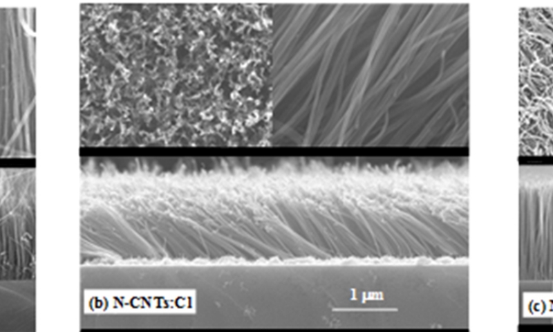
Figure 1(a), 1(b) and 1(c) shows the typical FE-SEM images of N-CNT, N-CNT:Cl and N-CNT:O respectively. It is clearly observed from the cross-sectional SEM-images, that the vertical alignment of N-CNT is changed on chlorine-plasma treatment, but strongly vertically, alignment is formed when the treatment was performed with oxygen-plasma. In general, the mechanism of the highly vertically aligned growth is mainly attributed to the high density of CNT being grown from the densely packed catalytic nano-particles. As the nanotubes lengthen, they interact with nearby nanotubes, presumably by van der Waals forces, to form a large bundle with some rigidity, which enables them to keep growing along the same direction19. On the basis of this growth mechanism, the alignment is changed on chlorine/oxygen-plasma treatments. Simultaneously, the density as well as the lengths of the tubes is decreased on chlorination but on oxidation it increased that can be observed from the overview and cross-section SEM-images shown in Figure 1. The increase (decrease) of length and density of the nanotubes can be explained with respect to their growth mechanism. The diffusion and precipitation of the reactive carbon species are faster (slower) in oxidation (chlorination), resulting faster (slower) growth rate and increase (decrease) in nanotubes length as well as nanotubes density. During the process of oxidation (chlorination), probably larger (smaller) numbers of active carbon species are in nucleation site that enhance (reduce) the nanotubes density. However, it seems the diameters of the tubes are slightly increased (~29 nm) and decreased (~21 nm) on chlorine and oxygen-treatment respectively with respect to non-treated N-CNT (~26 nm) due to change of CNTs density.
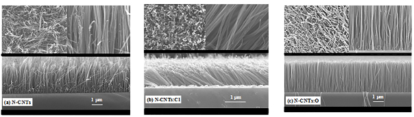
Figure 1. Typical Scanning Electron Microscopy images of (a) N-CNT, (b) N-CNT:Cl and (c) N-CNT:O.
3.2 Electron Field Emission
Conventional cathode ray tubes gradually being replaced; by flat panel displays20, where a continuous or patterned film of nanotubes provides a large number of independent electron beams. For this type of instruments, the field emission is one of the most promising applications for nanostructured carbon-based thin films. This can be attributed; to the recent development of cheap and robust field emitting materials and carbon nanotubes in particular have received much attention. In this process, when a high electric field in the order of 107 V/cm is applied on a solid surface with a negative electrical potential, electrons inside the solid are emitted into vacuum by the quantum mechanical tunneling effect. The carbon nanotubes are capable of emitting such high (electrons) currents (up to 1 A/cm2) at low fields (~5 V/mm) that are favorable for field emitters because of their high aspect ratio, sharp tip, high chemical stability and high mechanical strength. In particular carbon nanotube emitters21 are reported to be ideal candidates for the next generation of field emission flat panel displays22. Many experimental studies have been reported on field emission from multi-wall (MW) and single-wall carbon nanotubes (SWCNT)24-27, but the breakthrough for this technology came in 1998 when a crude display using nanotubes as emitters was first announced by Bonard et al.21 For a good emitter displays it is very essential to have the materials, which behaves high emission current density and at the same time the emission should be at very low threshold applied electric field. One process of field emission enhancement is functionalization of CNT using different precursors. Several field-emission studies have been reported to demonstrate the capability of carbon nanotubes to emit electrons with a high current density and threshold electric fields in the range 1-10V/mm21-28. Gohel et al.27 observed that the N2 treated MWCNT shows significant improvement in field emission properties, while the Ar+ treated MWCNT displayed poorer field emission characteristics compared to untreated MWCNT. Kurt et al.28 showed that the film of nitrogenated carbon nanotubes (N-CNT) behaves better field emission characteristics compared to CNT. We have studied the field emission effects on chlorine- and oxygen-plasma treatment of multiwalls N-CNT19, where we have found the turn-on applied electric field is less than 1.0 V/mm.
Figure 2(a) shows the results of the field emission measurements the current density (J) versus applied electric field (EA) and Figure 2(b) shows the Fowler-Nordheim (F-N) plot for the field emission on chlorine/oxygen-treated and non-treated N-CNT. Chlorine treated N-CNT shows field emission is enhanced, whereas on oxygen treatment this field emission is reduced compared to the non-treated N-CNT. Inset Figure 2(a) is the magnified lower part of J Vs EA of N-CNT and N-CNT:O to see the difference of J among them. The turn-on electric field (ETO) of non-treated N-CNT is 1.0 V/mm that we obtain from the F-N plot as plotted in Figure 2(b). Interestingly, this ETO is significantly reduced to 0.875 V/mm on chlorine treatment and increased slightly to 1.25 V/mm on oxygen treatment of N-CNT. Further, we have also obtained the field-emission current density in the mA/cm2 range for chlorine treated and non-treated N-CNT, but this current density is reduced to µA/cm2 on oxygen treatment. In terms of magnitude concern, the emission current density is enhanced for chlorine treated N-CNT (≈15 mA/cm2) with compared to non-treated N-CNT (≈1.3 mA/cm2) at EA=1.9 V/mm. However, in contrast, for our oxygen treated N-CNT the electric current density is reduced drastically (~0.0052 mA/cm2) at same EA=1.9 V/mm obtained from Figure 2. It is noted to be that all these measurements were confirmed by repeating them at several points through the samples surfaces. This enhancement and reduction of field emission on chlorine/oxygen treatment is attributed not only the change of physical properties but also depend on change of chemical properties that occurs during the process of treatment. In terms of physical changes: it is observed from the SEM-images as discussed above that the density is decreases, nanotubes length is shortened and the orientation is changed on chlorine treated N-CNT, whereas opposite trends is observed for oxygen treated N-CNT as shown in Figure1(b) and 1(c) respectively. The N-CNT:Cl may be considered as the medium-density based nanotubes as explained by Bonard et al.29 There have been several reports that show that the density and the orientation of the carbon nanotubes affect the emission characteristics29-31. The CNT thin films having high-density shows poorer quality of emission with compared to one that has medium density due to screening effects20,21. On the basis of density concern, it was observed by Bonard et al.21 that the field amplification factor optimizes once the intertube distance is twice the height of the carbon nanotubes and drops rapidly with decreasing the distances among the nanotubes. Moreover, the nanotubes cannot be too far apart as well since the number density of emitters decrease with increasing intertube distance. Again, if the numbers of emitters are very few then nanotube films become an ineffective cathode. Based on this argument, the field emission can be enhanced by properly reducing the surface density of the nanotubes as partially can be explains why the chlorine-treated N-CNT is higher field emission and have lower turn-on field compared to non-treated N-CNT. In case of oxygen treated N-CNT, the density and length of tubes become higher than non-treated and chlorine treated N-CNT as we observed in the SEM-images shown in Figure 1. As a result, the field emission is reduced with compared to pure N-CNTs and N-CNT:Cl. Chen et al.31 discussed for aligned/randomly oriented CNT having less densities are the higher emission due to two sources: (i) the small fraction of the CNT that point to the current collector due to simple statistical distribution and (ii) due to the field induced alignment. Several experiments have shown the CNTs can be easily bent and aligned to the electric field direction under a moderate electric field. Another advantage of this type of cathode is the large number of CNT available for emission that can lead to a longer lifetime. However, the optimal surface morphology is not the only reason for the enhancement/reduction of field emission characteristics, but the chemical functionalization or chemical doping sites also as to be taken into account for the enhanced field emission.
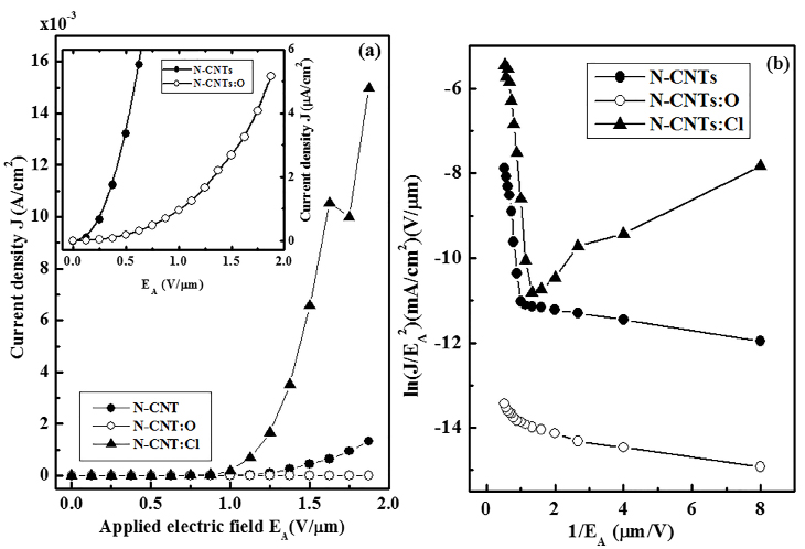
Figure 2. (a) The emission current density (J) with applied electrical field (EA) of N-CNT, N-CNT:Cl and N-CNT:O. Inset shows the magnified lower part of J Vs EA of N-CNT and N-CNT:O. (b)Field emission Fowler-Nordheim plots i.e. (1/EA) versus (J/EA2) of N-CNT, N-CNT:Cl and N-CNT:O.
We have studied the electron field emission effects on chlorination (N-CNT:Cl) and oxidation (N-CNT:O) of N-CNT. On chlorination high current density (J) of 15.0 mA/cm2 has been achieved, but on oxidation the current density (J) is reduces to 0.0052 mA/cm2 with compare to J=1.3 mA/cm2 for N-CNT at an applied electric field EA of ~1.9 V/mm. The turn on electric fields are changed from ETO=1.0 V/mm for untreated N-CNT to ~0.875 V/mm and 1.25 V/mm on chlorination and oxidation respectively. These findings are due to not only the change of optimal surface morphology but also the formation of different bonds with carbon and nitrogen in the N-CNT during the process of chlorine (oxygen)-plasma treatment that changes the density of free charge carriers and hence enhanced (reduced) the field emission properties of N-CNTs:Cl (N-CNTs:O).
3.3 Raman spectroscopy
We have measured the Raman spectra using the laser excitation energy having wavelength 633 nm as shown in Figure 3 and found that all N-CNTs have D-peak (~1330 cm-1) and G-peak (~1583 cm-1) along with a very weak T-peak (1156 cm-1). We observed that the ID/IG ratio changes from 1.34 (N-CNT) to 1.44 (N-CNT:Cl) and 1.40 (N-CNT:O) on chlorination and oxidation respectively. Higher ID/IG ratio in case of N-CNT:Cl caused increased the number of defects that enhance the field emission properties of N-CNT:Cl32. In our earlier reports we have discussed the electronic structure of N-CNT and N-CNT:Cl and N-CNT:O with the help of experimental results of x-ray absorption near edge structure (XANES) spectroscopy, scanning photoelectron microscopy (SPEM) and also theoretical calculation of density of states of N-CNT/ N-CNT:Cl/ N-CNT:O17,31. The overall field emission improvement of N-CNT:Cl is due to an etching effect on Cl-plasma treatment with the formation of C-Cl bonding after reducing the a-C content and overall increase of density of states17,31. We had seen an extra peak in between π* and σ* peak of C K-edge XANES spectra and the peak was attributed as the C-Cl rather than other bonding, which was formed by the substitution of C-C bonds. In case of N-CNT:O, the π* feature was quite close to that of HOPG and lies below the π* feature of non-treated N-CNT by ~1.1 eV that caused by the charge transfer process and the formation of C-N/N-O and/or C-O bonds. We also measured the relative sp2-content from the earlier reported x-ray absorption near edge structure (XANES) spectroscopy17,31 and found that sp2-content is decreases from 7.23 (N-CNT) to 7.09 (N-CNT:O) and 6.63 (N-CNT:Cl) on oxidation and chlorination respectively. In principal, the FE is enhanced with increase of sp2-content due to increase of graphitization in CNTs. But in our present case, this hypothesis does not support for N-CNT:Cl. So, the mechanism is different and caused due to formation of C-Cl bonding on chlorination that enhance FE properties.
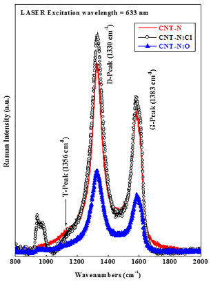
Figure 3. Room temperature Raman spectra of N-CNT, N-CNT:Cl and N-CNT:O at a laser excitation energy 1.96 eV (λ=633 nm from He-Ne laser).
The findings mentioned above, further confirmed by the theoretical calculation of PDOS of both N-CNT:Cl and N-CNT:O17,31. This evidence clearly indicated that the chlorine treated N-CNT is chemically functionalized and formed C-Cl bond that increase the density of free charge carriers and is responsible for the enhancement of the field emission characteristics. In oxygen treated N-CNT, the field emission is reduced due to decrease of the density of free charge carriers by the formation of more and comparatively dense nanotubes as observed in SEM micrograph in Figure 1(c) along with different bonds after chemically oxidation on the surface of nanotubes wall. During the Cl-plasma process, Cl ions with energy corresponding to the applied plasma power bombarded the tube wall and take carbon atoms away and changed into forms of C-Cl bonds. Due to lack of carbon in the ambience, a large fraction of C-Cl was taken out of the chamber with the Cl, which resulted in some nanotubes disappeared, and thus the CNT films become thin and dilute. Meanwhile, a small fraction of C-Cl re-deposited on the survived tube surface, which consequently caused many nano-scale particles along the remained tubes. These nano-scale particles are also may be caused to enhancement of field emission characteristics. We also observed in SPEM results that the spectra of N-CNT:Cl (N-CNT:O) broadens (shrunken) and shifted at higher (lower) energy of the σ bond feature and also increase (decrease) its intensity. The change in the σ-bond feature is associated with chlorine-derived (oxygen-derived) σ states and can be caused by the formation of C-Cl (N-O) bonds by the substitution of C-C bonds. It was explained that the broadening of σ bond in N-CNT:Cl may caused about the formation of sp3-like bond instead of sp2-like configuration, typical for graphite-like as proposed by Obraztsov et al.33,34 This change in co-ordination would decrease the height of the potential barrier and hence increase the field emission properties. The opposite features was observed for the N-CNT:O as a results the field emission properties reduced. Formation of N-O (C-Cl) on oxidation (chlorination) could also been explain with the Pauline electro-negativity process. The formation of N-O and probably sp3 C-N bonds caused by the transfer of electrons from the tube walls due to higher electro-negativity of oxygen/nitrogen than carbon [O (3.44)> N(3.04)> C(2.55)], whereas the C-Cl and sp2 C-N bonds are caused due to higher electro-negativity of chlorine/nitrogen than carbon [Cl (3.16)>N (3.04)>C (2.55)]. The increase (decrease) of length and density of CNT-N is also caused may be due to chemical interaction with Cl and O with N-CNT that forms C-Cl/N-Cl and N-O/C-O respectively. The N-O and sp3 C-N may cause the reduction of field emission properties of N-CNT:O by the decrease of density of free charge carriers and the C-Cl with sp2 C-N bonds causes the increase of electron affinity by the increase of density of free charge carriers and hence thereby enhanced the field emission properties of N-CNT:Cl.
3.4 Electronic structure and bonding properties
3.4.1 Chlorine functionalization of nitrogenated carbon nanotubes (N-CNTs:Cl)
Carbon nanotubes (CNTs) have attracted extensive attention, partly owing to their favorable electronic properties35. The doping of nitrogen impurities in CNTs was found to be a possible route to tune the band gap such that CNTs can be exploited to make various electronic devices9. However, direct doping of nitrogen impurities is not the only way to control the electronic property; chemical modification and/or purification of the CNTs can also alter the electronic properties and improve the performance of various devices. The fluorinated CNTs can be tuned from metal to semiconductor/insulator with high resistivity at elevated temperatures36. Fluorination can also improve the wetting of nanotubes in water by inducing a surface dipole layer on the nanotube wall. This effect may be useful in battery and super-capacitor applications37. Iodine- and bromine-doped CNTs were found to enhance the electronic/electrical properties by increasing the density of free charge carriers38. Therefore, it is interesting to understand the effect of chemical modification of CNTs using halogens (F, I, Br and Cl). Fluorine-, iodine- and bromine-treated CNTs36,37 and CNTs-based nanomaterials39,40,15,19 have been investigated previously. The electronic and bonding properties of chlorine-treated nitrogenated carbon nanotubes (N-CNTs:Cl) has not been fully carried out. Therefore, a comprehensive study of the electronic structures and bonding properties of N-CNTs:Cl is complementary to the understanding of the properties of halogen modified CNTs. Here, the electronic structures and bonding properties of freshly prepared N-CNTs, which were further treated with chlorine-plasma in an inductively coupled plasma system, have been studied using x-ray absorption near-edge structure (XANES) and scanning photoelectron microscopy (SPEM).
Figure 4(a, b) displays C K-edge and N K-edge XANES spectra of N-CNTs with and without chlorine treatment and the highly oriented pyrolytic graphite (HOPG) as a reference. The feature with the maximum intensity at approximately 285.5eV for HOPG was attributed to the π* antibonding state originated from the out-of-plane bonds in the sp2 bonding configuration41. The positions of π* resonance feature in the C (1s) XANES spectra of N-CNTs and N-CNTs:Cl located at ~286.4 and 286.7 eV, respectively, which are shifted by ~ 0.9eV for N-CNTs and 1.2eV for N-CNTs:Cl with respect to that of HOPG (285.5eV), correspond to the 1s→ π*(e2u) transition as in the pyridine-like sp2 C-N structure42. Pyridine is also well known to have two unfilled π* orbitals (as in benzene) with e2u (an anti-bonding state whose wave functions are anti-symmetric) and b2g (a bonding state whose wave functions are symmetric) symmetry42. The latter is observed at ~289.2eV in the π* region for N-CNTs:Cl, and its intensity increases with the Cl-treatment time. This feature is attributable to the transition of 1s→ π*(b2g) similar to that of the pyridine structure with the symmetric bonding state11, and/or C-Cl bonds, as observed by Unger et al. at 289.0eV in x-ray photoelectron analysis of Cl-functionalized multi-wall CNTs43. Previous works of carbon systems revealed a similar double feature in the C (1s) XANES spectra44. For N-CNTs, a small shoulder observed at ~289eV (indicated by a vertical arrow) was attributed to the presence of interlayer graphite states, which was correlated with the calculated electronic state of dual-layer graphite sheets45. In the σ* region, the centers of the maximum features of N-CNTs and N-CNTs:Cl appear at ~293.2 and 293.6 eV respectively, similar to those of the pyridine structure42. Interestingly, the intensities of 1s→ π*(e2u) (286.4/286.7 eV) and σ* (293.2/293.6 eV) features decrease, while that of 1s→ π*(b2g) feature (indicated by the arrow) increases with the increase of Cl-treatment time as clearly shown in the inset of Figure 4(a). This trend suggests the formation of a more symmetric bonding state in the N-CNTs than in the pyridine structure.
To identify clearly these features, the p-projected conduction-band partial densities of states (PDOSs) of pure CNTs, N-CNTs and N-CNTs:Cl are calculated using the CASTEP code46, which is a plane-wave pseudopotential program based on the density functional theory and local density approximation, and are shown in Figure 5. The benzene, pyridine and pyridine-Cl cluster models are employed to represent local bonding configurations of CNTs, N-CNTs and N-CNTs:Cl, respectively. The hydrogen atoms in these models saturate the dangling bonds of carbon atoms, so that these carbon atoms mimic those in CNTs, N-CNTs and N-CNTs:Cl. The insets (a)-(c) in Figure 5 present the bonding configurations of these three CNTs; blue and green colors in the bonding structures indicate the attachment of N and Cl atoms in pure CNTs, respectively. Details of the calculations for the cluster models of these CNTs with various geometries can be found elsewhere47.In Figure 5, the feature located at ~2.6eV between π* and σ* for the cluster model of pyridine-Cl may correspond to the extra feature indicated by the arrow between π* and σ* features in the inset of Figure 5 and can be attributed to the C-Cl bond. This feature [C 1s→ π*(b2g) at ~289.2eV] is much more prominent in the N K-edge XANES spectra of the N-CNTs and N-CNTs:Cl to be described below.
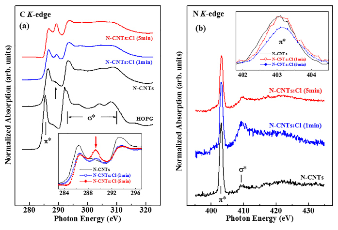
Figure 4. (a) C K-edge XANES spectra of unchlorinated/chlorinated N-CNTs and reference HOPG. The inset highlights the π* region. (b) N K-edge XANES spectra of unchlorinated/chlorinated N-CNTs. The inset highlights the π* region.
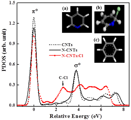
Figure 5. The PDOSs of various CNTs. Insets (a), (b) and (c) show the cluster models, which represent the local bonding configurations of CNTs, N-CNTs and N-CNTs:C, respectively. Blue- and light-green colored balls indicate N and Cl atoms, respectively.
Figure 4(b) displays the N K-edge XANES spectra of the N-CNTs and N-CNTs:Cl samples. The two main features centered at ~403.2 and ~409.5 eV, are associated with transitions into unoccupied π* and σ* orbitals, respectively. As stated above, the pyridine structure has two unfilled π* orbitals with e2u and b2g symmetries, which are typically observed in the N K-edge XANES spectra at ~400.0 and ~403.7 eV, respectively, for nitrogenated carbon films42. The features in the N K-edge XANES spectra in Figure 7 are similar for all N-CNTs. The prominent feature centered at ~403.2eV in the π* resonance has the b2g symmetry of the pyridine structure42. Jimènez et al.48 also observed this feature at 403.5eV for sp2-hybridized nitrogenated carbon films, for which the π* region can be resolved into four peaks. The broad feature centered at ~409.5eV in the σ* region is associated with the C-N bond and is identical to that of the pyridine structure.42,48 The inset in Figure 7 reveals that the intensity of the π* features in the N K-edge XANES spectra decreases with the Cl-treatment time in consistent with the trend of the C K-edge XANES spectra shown in the inset of Figure 4(a), which consistently indicate that Cl-treatment increases the occupation of the b2g symmetry states or enhances the pyridine-like C-N bonding.
Figure 6 displays spatially resolved valence-band photoemission spectra of N-CNTs and N-CNTs:Cl with corresponding C 1s SPEM cross-sectional images. The bright area in the SPEM image corresponds to the N-CNTs and N-CNTs:Cl with a maximum C 1s intensity. The spectra presented in Figure 6 exhibit photoelectron yields from the bright regions S0 (N-CNTs), S1 (1 min Cl-treated) and S5 (5 min Cl-treated), which correspond to the sidewalls of the respective N-CNTs, N-CNTs:Cl (1 min) and CNTs:Cl (5 min). The zero energy refers to the Fermi level (Ef), which is the threshold of the emission spectrum. The spectra contain two weak structures at binding energies of ~3.5 and 8.2 eV (shown by down arrows) associated with the C 2p π- and σ-bonds, respectively49-51. The spectra of N-CNTs:Cl (1 min) and CNTs:Cl (5 min) show that chlorine treatment of N-CNTs broadens the feature of the σ bond and increases its intensity. The change in the σ-bond feature may be associated with chlorine-derived σ states and can be caused by the formation of C-Cl and/or N-Cl bonds. However, the physical origin of this feature remains uncertain. Features observed at ~15eV (mixed s and p character of the C-N bond) and ~19eV (C 2s) are typically observed in nitrogenated carbon films with a graphitic structure52. The intensities of these two features (~15 and 19 eV) decrease with the chlorine treatment, while the intensity of another new feature in the 24-30 eV range (centered at ~26eV), which is attributable to N 2s states, increases with the chlorine treatment. This result reflects the increase and decrease of the numbers of C-N and C-C bonds, respectively, and the formation of a pyridine structure in nitrogenated carbon films as described by Bhattacharyya et al. for nitrogenated carbon films52. The N 2s peak is very prominent, despite that the N/C at% ratio is only 0.033 (for N-CNTs) and 0.054 (for N-CNTs:Cl), which may suggest that N 2s orbital has a larger effective cross-section area or transition probability than those of C valence orbitals for the 388eV photon. This feature is observed in various nitrogen-based materials and its intensity increases with the nitrogen concentration53. The increase of the intensity of this feature is also consistent with the increase of the N/C at% ratio from 0.033 (N-CNTs) to 0.054 (N-CNTs:Cl) revealed by x-ray photoelectron spectroscopy. The difference between N-CNTs:Cl and N-CNTs spectra as shown in the lower inset of Figure 6 illustrates the effect of the treatment of N-CNTs with chlorine. The difference spectra contain two positive features in the π and σ regions (within the range: 0-9 eV) and another feature (in the 24-30 eV range) centered at ~26eV. A negative feature centered at ~18eV is a signature of the decrease in the number of C 2s bonds, which is consistent with an increase of the intensity of the feature at ~26eV and the formation of the C-N bond. It may also be associated with the formation of either C-Cl and/or N-Cl bonds by the substitution of C-C bonds.
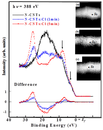
Figure 6. Valence-band photoemission spectra obtained from selected bright-spot S0, S1, and S5 of C 1s SPEM cross-sectional images of unchlorinated/chlorinated N-CNTs at the excitation photon energy of 388 eV. The inset shows difference between N-CNTs:Cl and N-CNTs spectra.
The increase of the intensity of the feature between π* and σ* in the C K-edge XANES spectra (at ~289.2eV in the inset of Figure 4a) and the C-Cl bond peak (at ~2.6eV shown in Fig. 5) in the calculated conduction-band PDOSs are a strong evidence of the contribution of C-Cl bonds in N-CNTs:Cl. The decrease of the intensity of the π* feature (shown in the inset of Figure 4(b)) and the increase of the intensity of the feature at ~289.2eV (shown in the inset of Figure 4a) with the increase of the Cl-treatment time in the N K-edge and C K-edge XANES spectra, respectively, indicate the formation of sp2 C-N bonded N-CNTs with more symmetric pyridine-like structures. In the case of SPEM shown in Figure 6, chlorine treatment of N-CNTs broadens the p-σ bond associated with chlorine-derived σ states and markedly increases the intensity of the new feature at ~26eV, which is attributable to N 2s states53 and this highly sensitive N signal may indicates the presence of N on the surface of CNTs. These observations in conjunction with the theoretical calculation suggest that the formation of pyridine, the increased symmetry of the N-CNTs states, and the possible formation of mixed C-Cl, N-Cl and sp2 C-N bonds are due to chlorination. Upon chlorination, the absorption edge of the N K-edge XANES spectra are shifted slightly towards higher energies than that of untreated N-CNTs (as shown in the inset of Figure 6), suggesting an increase in the nitrogen concentration caused by the substitution of carbon atoms by nitrogen atoms, which was argued to give rise to the upward band bending9, because nitrogen is more electronegative than carbon, so that substitution of carbon by nitrogen yields accepter-like states. Band bending can also be caused by the substitution of chlorine, because it also has a greater electronegativity than carbon, which increases the density of free charge carriers and improves the electronic and electrical properties of N-CNTs:Cl.
3.4.2 Chlorine / Oxygen functionalization of nitrogenated carbon nanotubes (N-CNTs:Cl & N-CNT:O)
Oxygen and halogen (F, I, Br and Cl) funtionalization of CNTs and/or C60 are also another approach for modifying the electronic, electrical and mechanical properties to use in suitable electronic applications59-60. Particularly, much attention has been directed to reveal the electronic structure of the N-CNTs due to their diverse structures, such as graphite-like, pyridine-like, cross-linked sp3 and pyrrolic that are identified by electron energy-loss spectroscopy (EELS) and x-ray photoelectron spectroscopy (XPS)54,55. Despite of those works, still the interpretation of these spectra are a matter of long lasting controversy56. But the x-ray absorption near edge structure (XANES) and scanning photoelectron microscopy (SPEM) are more advance and informative techniques for the study of electronic structure of CNTs. In the above, we have studied the electronic structure of chlorine treated N-CNTs using XANES / SPEM and clearly identified the structure (pyridine-like)9 of the CNTs. Now, we have studied and compared the electronic structure and compared the formation of different structure using XANES and SPEM of with/without oxygen and chlorine treated (functionalization) N-CNTs. Details of XANES and SPEM measurements are described in our previous report57 “the electronic structure of tips and of sidewalls” of CNTs.
For the study we have prepared three different kinds of nitrogenated carbon nanotubes (N-CNTs) on Si (100) substrate: (i) N-CNTs prepared by microwave-plasma enhanced chemical-vapor deposition (MPECVD) using Fe catalys19 under identical conditions (Power = 2KW, Gas flow rates ⇒ CH4/H2/N2=20/80/80 sccm, Ptotal=45 Torr, Tsub=1000° C and tdep.=10 min). Afterwards, these N-CNTs were treated using (ii) oxygen (N-CNT:O): Air-atmospheric plasma condition using dielectric barrier discharge system58 at a discharge power of 200W and (iii) chlorine (N-CNT:Cl): Inductively plasma coupled reactor at a 5 sccm flow rate of Cl gas for 1 min having the total pressure of 40 mTorr and power 150W.9 High-resolution scanning electron microscope (HRSEM) images of all N-CNTs measured to see the microstructure of these CNTs using the Philips CM200 as shown in Figure 1; where we observed from the cross-sectional images that the N-CNT:O exhibit highly dense vertical-oriented and N-CNT:Cl is less dense non-vertical-oriented CNTs with compare to non-treated N-CNT. This indicates that in oxygen treatment modified and preserved the structural integrity but under chlorine treatment does not preserved the structure of the N-CNTs.
Figure 7(a, b) shows the C K-edge and N K-edge normalized XANES spectra of three different N-CNTs and highly oriented pyrolytic graphite (HOPG) as a reference. The energy calibration has been done with the π* resonance peak of HOPG at 285.5 eV, corresponds to the lowest-lying state of π symmetry po, near Q in the Brilloun zone of graphite41. The π* resonance peak positions in C (1s) XANES spectra of N-CNT, N-CNT:O and N-CNT:Cl are at ~286.4, ~285.2 and ~286.7 eV respectively. It is remarkable noticed that this π* peak positions are not identical of all N-CNTs. This is due to formation of different structure of N-CNTs. The peak position of N-CNT:O at 285.3 eV, which is very near to the π* resonance of HOPG (285.5 eV) and is assigned as the graphite structure41, whereas other two CNTs peaks are at 286.5 eV (N-CNT) and 286.7 eV (N-CNT:Cl), which are corresponding to 1s→π*(e2u) transition similar to pyridine structure41. It is well know that the pyridine has two unfilled π* orbital (like in benzene) with e2u (anti-bonding state where wave functions are anti-symmetric) and b2g (bonding state where wave functions are symmetric) symmetry41. The former peak is also observed at ~ 289.4 eV in the π* region in case of N-CNT:Cl and is due to the transition of 1s→π*(b2g), similar to that of pyridine structure with symmetry bonding state14. A similar double peak in the C (1s) XANES has been reported in several previous studies of carbon systems and identified as carbon nanotube features59. However, Ray et al.60 observed similar peak within the range 288-290 eV in a-C:H(OH) film and assigned as C=O π* bond. But this peak does not appear in N-CNT:O that may be expected due to oxidation, which confirms the peak is not C=O π* bond in the present case the N-CNT:Cl and even not of C-Cl bonding state due of absence of this peak in the absorption spectra of CCl4 at the C 1s edge61 . Again in case of N-CNT as well as in HOPG, a shoulder is observed at ~ 288.6 eV which is the existence of interlayer graphite states62 and are correlated to the band structures calculation on dual-layer graphite sheets62. So, it clear that the peak observed at 289.4 eV in N-CNT:Cl is the transition of 1s→π*(b2g) having symmetric pyridine-like N-CNT structure. In the σ* region of the C K-edge also shows similar structure as we observed in π* region as clearly shown in inset Figure 9, i.e. (i) for N-CNT:O the peak appear at 292.1 eV and is the transition from s1, s2: Γ→Q state of graphite19,41,63 and (ii) for N-CNT and N-CNT:O; the peaks are appeared at 293.6 eV and 293.2 eV respectively, which are similar to that of pyridine structure41.
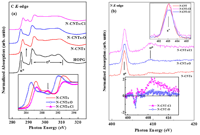
Figure 7. (a) C K-edge XANES spectra of non-functionalization and oxygen/chlorine functionalization nitrogenated carbon nanotubes along with HOPG reference. Inset shows the overlap π* region of all CNx-NTs. (b) N K-edge XANES spectra of non-functionalization and oxygen/chlorine functionalization nitrogenated carbon nanotubes. Inset shows the overlap π* and σ* region of all CNx-NTs.
To identity these features, the PDOSs of treated (N-CNTs:Cl and N-CNTs:O) and untreated N-CNTs and CNTs are calculated using the CASTEP code64, which is a plane-wave pseudopotential method based on the density functional theory and the local density approximation (shown in Figure 8). The benzene, pyridine, pyridine-Cl, and pyridine-O cluster models represent the local bonding configurations of CNTs, N-CNTs, N-CNTs:Cl, and N-CNTs:O, the dangling bonds of carbon atoms. Insets (a)–(d) in Figure 8 display the bonding configurations of these four CNTs using blue (N), green (Cl), and red (O) colors which represent the bonding atoms in pure CNTs. Details of the calculations using the cluster models of these CNTs with various geometries can be found elsewhere65. In Figure 8, the first feature in the calculated PDOSs has been aligned with the first feature (π*) in the XANES spectra and the unit of intensity has been arbitrarily normalized. The feature at ~2.6 eV between π* and σ* is obtained from PDOSs of the cluster model of pyridine-Cl with small shift of σ* at higher energy that corresponds to the C–Cl bond feature observed in C K-edge XANES spectra, as indicated by the arrow in the inset of Figure 7(a). According to the cluster model of pyridine-O in Figure 8, the σ* feature is shifted toward lower energy, as also shown in Figure 7(a), due to the formation of more sp2-bonded graphitic carbon in the N-CNTs:O observed by Nevidomskyy et al., who found that the sp2-bonded carbon feature shifted toward the lower energy in PDOSs calculation of N-CNTs66.
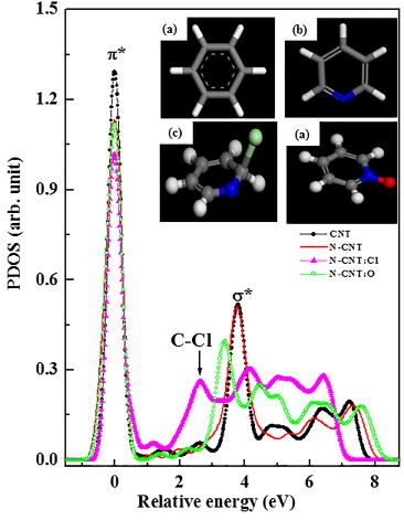
Figure 8. The PDOSs of various CNTs. Insets (a), (b), (c) and (d) show the cluster models, which represent the local bonding configurations of CNTs, N-CNTs, N-CNTs:Cl and N-CNTs:O respectively. Blue-, light-green and red colored balls indicate N, Cl and O atoms, respectively.
In N K-edge spectrum shown in Figure 7(b), consist of two main features centered at ~ 403.2 eV and ~ 408.5 eV. The former and later features are assigned to the transition into unoccupied π* and σ* orbital respectively. We have discussed about the pyridine structure and it has two unfilled π* orbital with e2u and b2g, which are also generally observed in the N K-edge at ~ 400.0 eV and ~ 403.7 eV respectively14. The general features of the present N K-edge XANES spectra shows in Figure 3, are similar for all N-CNTs. A strong peak centered at ~ 403.2 eV in the π* resonance, probably with b2g (bonding state where wave functions are symmetric) symmetry pyridine structure41. Jimènez et al.67 also observed this peak at ~403.5 eV for sp2-hibridized a-CNx film after resolving the π* region into four peaks. The wider peak at ~ 408.5 eV in the σ* region is also appear from C-N bond and is expected to the identical with pyridine structure41,67.
Figure 9 shows the C 1s SPEM cross-sectional images and corresponding valence-band photoemission spectra (PES) recorded from the bright spot (S1, S3, S6) of N-CNTs. In valence band PES, the general spectral features are different for all N-CNTs and shows two weak structures at binding energies of ~3.5 eV (marked by arrow mark) and ~8.2 eV, associated to π and σ bonds respectively8,68. Due to chlorine/oxygen treatment on N-CNT a new small peak arises at ~11.5 eV, which is attributed to p-σ contribution of C-N bonds61,62. Peaks observed at ~14.5 eV (mixed of s and p character of C and N bond) and ~18.5 eV (C 2s) are generally observed in graphitic structure a-CNx film51. The intensities of these two peaks (14.5 eV and 18.5 eV) are decreases for N-CNT, whereas the intensity of another additional new peak appears at ≈ 25.0 eV for both N-CNT:O and N-CNT:Cl having different intensities and assigned as the N 2s states.51 This reflects the substitution of C-C bonds by C-N bonds due to decrease (increase) of carbon (nitrogen) at% and formation of pyridine structure as described by Bhattacharyya et al.51 and is well agreement with the increase of N/C at% ratio obtained from XPS compositional analysis (0.033 for N-CNT, 0.047 for N-CNT:O and 0.054 for N-CNT:Cl respectively). Difference of N-CNT spectra from N-CNT:O and N-CNT:Cl spectra may be used to understand the effect of oxidation and chlorination on N-CNT as shown inset Figure 9 below. The difference shows positive intensity in the π and σ region for chlorinated N-CNT and a peak at ~24.0 eV for both oxygen and chlorine treated spectra. A negative intensity at ~ 18.0 eV for both spectra is a signature of the decrease of C 2s bond that consistent with positive intensity of the peak ~ 24.0 eV and formation of C-N bond.51
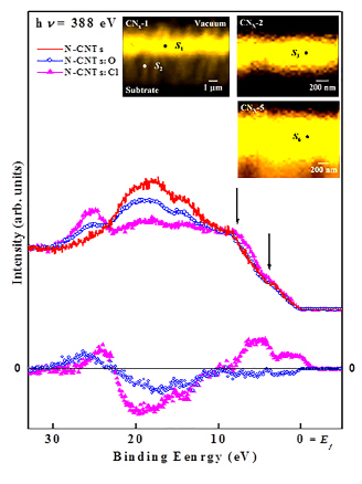
Figure 9. Valence-band photoemission spectra of non-functionalized and oxygen/chlorine functionalized nitrogenated carbon nanotubes obtained from selected bright spot S1, S6, and S5 of C 1s SPEM cross-sectional images. Inset the high-resolution scanning electron microscopy cross-sectional and top-view images.
The results discussed above all together confirm that on oxidation N-CNT becomes graphite-like structure (N atoms replacing C atoms in graphite layer) whereas on chlorination it becomes pyridine-like and more symmetric structure N-CNT. Upon chlorination, the absorption edge of C K-edge XANES spectra is shifted rigidly towards higher energy by ~ 0.6 eV, whereas on oxidation this absorption edge shifted towards lower energy (inset Figure 2) by ~ 1.0 eV as compared to non-treated N-CNT. This can attribute to the upward and downward band bending respectively69. The band shift of π and σ in valence band spectra is not noticeably observed for oxidative N-CNT, but chlorinated N-CNT shows a very small (≈ 0.1 eV) band shift towards higher binding energy. This shift can be attributed to the rise of Fermi level69 due to substitution of carbon by the nitrogen and/or may be chlorine atoms that well agreement with the absorption edge shift in C K-edge XANES spectra.
3.5 Magnetization (M-H loop)
The magnetization M-H hysteresis loop of MW-NCNTs obtained at 300 K and 5 K is shown in Figure 10(a). The spectral features behaviours unambiguously implies a diamagnetic response, although the CNTs have contribution of magnetic Fe-particles. We emphasize that the spectra at T = 5 K strongly confirms the diamagnetic behavior of this N-CNTs. Lipert et al.71 observed the similar diamagnetic behavior of Fe-based MWCNTs, after post annealing process at 25000C temperature. They have claimed that the ferromagnetic behavior changed into diamagnetic due to complete evaporation of Fe-catalyst particles from the CNTs at this higher annealing temperature. But, we do follow any post annealing process and shows diamagnetic behavior as synthesized CNTs that shown in Figure 10(a). Furthermore, the chlorine and oxygen functionalized MWNCNTs shows the ferromagnetic behavioral M-H hysteresis loop unlike non-functionalized MW-NCNTs as shown in Figure 10(b and c). Bianco et al.72 also observed the ferromagnetic behavioral M-H loop for the core interface of oxygen passivated Fe-nano-particles. In our case it may occur due to both of chlorine as well as oxygen passivation with the N-CNTs on oxidation as well as chlorination. The thermal evolution of the magnetization measurements temperature (T) dependence magnetization (M) were further characterized for all CNTs (functionalized/non-functionalized) by the zero-field-cooling (MZFC) and field-cooling (MFC) procedures in an applied magnetic field of 50 Oe, 200 Oe and 1000 Oe respectively in between 5 K and 300 K. Figure 10(d) shows the M-T curve of N-CNTs; whereas N-CNT:Cl and N-CNTs:O shown in Figure 10(e and f) respectively. It shows the MZFC curve gradually deviates from the MFC curve with decrease of temperature at about 280 K, when magnetic field is applied 50 Oe for the N-CNTs and is further decrease to 255 K at the applied magnetic field 1000 Oe. Upon further cooling, the MZFC plot exhibits a cusp centered at about 45 K, and the MFC data sequentially increases when magnetic applied field was changed from 50 to 1000 Oe as shown in Figure 10(d). This variable temperature magnetic data clearly indicate that the Fe/N-CNTs exhibit weak ferromagnetic behavior at below room temperature, which is attributed to the uncompensated surface spin states or ferromagnetic Fe clusters. As a result, it is believed that the weak ferromagnetic performance of the Fe/N-CNTs comes from the ferromagnetic Fe clusters and the uncompensated surface spin states. This low temperature ferromagnetic phase magnetization is correlated to the fact that at lowest temperature and after MZFC process, the moments of magnetic particle Fe are not fully aligned with the applied field. Furthermore, no cusp is observed in the MZFC plot in N-CNT:Cl line N-CNTs indicating that after functionalization with chlorine (N-CNT:Cl), it becomes more diamagnetic in nature.
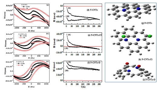
Figure 10. M-H Hysteresis loop of (a) NCNTs (b) chlorine functionalised NCNTs and (c) oxygen functionalised NCNTs. MFC and MZFC, M-T spectra of (d) NCNTs (e) chlorine functionalised NCNTs and (f) Oxygen functionalised NCNTs (see online version for colours). The most stable model complexes of (g) NCNTs, (h) chlorine functionalised NCNTs and (i) oxygen functionalised NCNTs (see online version for colours).
In case of N-CNT:O, it is found that the MZFC curve gradually deviated from the MFC curves with decrease of temperature at about 300 K as shown in Figure 10(f), when measured at an applied magnetic field of 1000 Oe. A similar behavior has been observed by Zhang et al.73 for CoO/CNTs core–shell nanostructures, when they have measured at an applied magnetic field 100 Oe between 2 K and 300 K. In our present case, it is also further observed upon further cooling that the MZFC plot exhibits a cusp centered at about ≈45 K and the MFC data sequentially increases indicates higher ferromagnetic behavior at this temperature compared to N-CNT and N-CNT:Cl. It is believe that this ferromagnetic behavior comes from the ferromagnetic Fe-clusters and uncompensated surface spin states, although M-H curve shown in Figure 10(a) is completely diamagnetic in nature. Room temperature diamagnetic behaviours have been studied for the N-CNTs and functionalized N-CNTs with oxygen and chlorine. The interaction between Fe-nanoparticles and the CNTs plays a critical role for the diamagnetic behavior of the Fe-catalyst based N-CNTs at room temperature. A very week ferromagnetic nature shows at lower temperature and is due to ferromagnetic Fe-clusters and the uncompensated surface spin states. It is believe that these magnetic N-CNTs(:Cl/O) may show promising applications in biomedicine and other bio-applications.
To identify the bonding features of pure NCNTs and Cl/O functionalised NCNTs (NCNTs:Cl and NCNTs:O); computational calculations were carried out using DFT based B3LYP method and 6-31G (d) basis set combination implemented in Gaussian 09 software program74. To generate the model we have used NCNTs and two most stable complexes of
• NCNTs with Cl2
• NCNTs with O2 that are shown in Figure 10(g)–(i).
The hydrogen atoms in these models saturate the dangling bonds of carbon atoms, so that these carbon atoms mimic those in NCNTs, NCNTs:Cl and NCNTs:O. For the N-doped model system, we got a very stable chemically bonded singlet structure. This N-doped system then used to study the interaction of Cl2 and O2 in their ground states. Fundamentally, when a singlet molecule (like Cl2) reacts with another system with singlet electronic configuration gives a singlet product, and when a triplet molecule (like O2) reacts with a singlet system gives a triplet product. So we have analysed nature of bonding in those two different products
• singlet NCNTs with Cl2
• triplet NCNTs with O2.
Analysis of the results shows that Cl2 reacts with NCNTs and the product obtained is in singlet state as shown in Figure 10(h). It can be seen that the Cl atoms are now dissociated and the nature of interaction between the NCNTs and the Cl-atoms are physisorption in nature. It is also interesting to note that the physisorption site for the Cl-atom is very specific and it prefers to stay above the C-atom of the NCNTs and not above the N-doped site. As the product is in singlet configuration, the electrons spins will be perfectly paired, but the electrons in both the Cl-atoms will precess in the presence of the magnetic field as they are almost in unbound states. The two magnetic vectors coming from the both the Cl-atoms will lie in the same plane with a well-defined phase relationship. It is well known that the condition for an effective transition from the singlet state to the triplet state is that the local fields must differ (even slight difference is effective) at the two electrons. Owing to the curved nature of the NCNTs, it can be easily expected that the electron on each Cl-atom must experience a slight difference in the local fields. As the two electrons are in the influence of different local fields, one of the electron vectors will precess at a greater rate than the other when a magnetic field is applied. This leads to periodic transition from singlet to triplet configuration. Such a behaviour will lead to the paramagnetic behaviour of a material system and in this light we think the Cl-doped system’s paramagnetic behaviour can be explained.
Analysis of the results shows that O2 reacts with NCNTs and the product obtained is in triplet state as shown in Figure 10(i). We did not carry out a complete potential energy search to ascertain if there are any other stable minima with other spin multiplicities or not. From the Figure 10(f) it can be seen that in the O2 doped case, O2 is chemically bound to the nanotube and not like the earlier case of Cl2 doping. This stable chemically bound state in the O2 case may be freezing the spins of the two unpaired electrons and parallelising the orientations of the two spin vectors. Only such phenomena can lead to a permanent magnet-like behaviour of the material system. In view of the experimental findings we can explain that the O-functionalised NCNTs to show the ferromagnetic type of behaviour it should definitely have a stable chemically bound state and spin bound conditions as shown here in this work. In light of such chemical structural feature with a spin bound triplet state only, one can explain why the O-functionalised NCNTs are ferromagnetic in nature.
4 Conclusion
In conclusion, we have studied and discussed the surface morphology, microstructural properties, electronic structure, bonding properties and change of magnetic behaviors of N-CNTs along with theoretical calculation for supporting these results of functionalized N-CNTs in oxygen [denoted as N-CNTs:O] and chlorine functionalized N-CNTs using different measurements. The electron field emission effects on chlorination (N-CNT:Cl) and oxidation (N-CNT:O) of N-CNT. On chlorination high current density (J) of 15.0 mA/cm2 has been achieved, but on oxidation the current density (J) is reduced to 0.0052 mA/cm2 compared to J = 1.3 mA/cm2 for N-CNT at an applied electric field EA of ~1.9 V/mm. The turn-on electric fields are changed from ETO = 1.0 V/mm for untreated N-CNT to ~0.875 and 1.25 V/mm on chlorination and oxidation, respectively. These findings are due not only to the change in optimal surface morphology but also to the formation of different bonds with carbon and nitrogen in the N-CNT during the process of chlorine (oxygen)-plasma treatment that changes the density of free charge carriers and hence enhances (reduces) the field emission properties of N-CNTs:Cl (N-CNTs:O).
The electronic and bonding properties of nitrogenated carbon nanotubes (N-CNTs) exposed to chlorine plasma were investigated and found that the C and N K-edge XANES spectra of chlorine-treated N-CNTs consistently reveal the formation of pyridinelike N-CNTs by the observation of 1s→π*(e2u) antibonding and 1s→π*(b2g) bonding states. The valence-band photoemission spectra obtained from SPEM images indicate that chlorination of the nanotubes enhances the C–N bonding. In case of oxygen- and chlorine-treated nitrogenated carbon nanotubes (N-CNTs) study the C K-edge XANES spectra are shifted by ~0.3 eV toward higher energies and by ~1.1 eV toward lower energies relatively to those of the more symmetrical pyridinelike and graphitelike structured N-CNTs upon chlorination and oxidation, respectively. Increases in N K-edge XANES intensities for both chlorination and oxidation reveal substitution of C–C bonds by C–N bonds consistent with the observed valence-band photoemission spectra of the decrease of the C 2s bond and the increase of the N 2s bond. First-principles calculations of the partial densities of states in conjunction with C K-edge XANES data identify the presence of C–Cl bonding in chlorine treated N-CNTs. The formation of more sp2-bonded graphitic carbon in the N-CNTs:O is observed and the sp2-bonded carbon feature shifted toward the lower energy as observed in PDOSs calculation of N-CNTs. Room temperature and below room temperature magnetic behaviours have been studied for the NCNTs and functionalised NCNTs with chlorine and oxygen. The interaction between Fe-nanoparticles and the NCNTs plays a critical role for the diamagnetic behaviour of the Fe-catalyst based NCNTs at room temperature. NCNTs:O show ferromagnetic nature at room/below room temperature and is owing to ferromagnetic Fe-clusters and the uncompensated surface spin states owing to formation of different bonding with carbon and/or nitrogen. It is believe that these magnetic/non-magnetic NCNTs (:Cl/O) may show promising applications in biomedicine/bio- and nano-electronics applications. From the computational results, we considered that the differential bonding patterns of the Cl-functionalised and the O-functionalised NCNTs are the main cause for the different magnetic behaviour of these systems.
Notes
The authors declare no competing financial interest.
Ackowledgements
S.C.R. gratefully acknowledge the financial support received from the National Research Foundation (NRF), South Africa (Grant No. EQP13091742446).
References
[1] Iijima S. Helical microtubules of graphitic carbon. Nature 1991;354(6348):56–8. doi:10.1038/354056a0
[2] Hamon MA, Itkis ME, Niyogi S, Alvaraez T, Kuper C, Menon M, et al. Effect of Rehybridization on the Electronic Structure of Single-Walled Carbon Nanotubes. Journal of the American Chemical Society 2001;123(45):11292–3. doi:10.1021/ja0109702
[3] Srivastava D, Brenner DW, Schall JD, Ausman KD, Yu M, Ruoff RS. Predictions of Enhanced Chemical Reactivity at Regions of Local Conformational Strain on Carbon Nanotubes: Kinky Chemistry. The Journal of Physical Chemistry B 1999;103(21):4330–7. doi:10.1021/jp990882s
[4] Zhao J, Lee CW, Han X, Chen F, Xu Y, Huang Y, et al. Solution-processable semiconducting thin-film transistors using single-walled carbon nanotubes chemically modified by organic radical initiators. Chemical Communications 2009;(46):7182. doi:10.1039/b915508b
[5] Gebhardt B, Graupner R, Hauke F, Hirsch A. A Novel Diameter-Selective Functionalization of SWCNTs with Lithium Alkynylides. European Journal of Organic Chemistry 2010;2010(8):1494–501. doi:10.1002/ejoc.200900848
[6] Dresselhaus MS, Dresselhaus G, Avouris P, editors. Carbon Nanotubes. Topics in Applied Physics 2001; doi:10.1007/3-540-39947-x
[7] Dettlaff-Weglikowska U, Skákalová V, Graupner R, Jhang SH, Kim BH, Lee HJ, et al. Effect of SOCl2Treatment on Electrical and Mechanical Properties of Single-Wall Carbon Nanotube Networks. Journal of the American Chemical Society 2005;127(14):5125–31. doi:10.1021/ja046685a
[8] Ago H, Kugler T, Cacialli F, Salaneck WR, Shaffer MSP, Windle AH, et al. Work Functions and Surface Functional Groups of Multiwall Carbon Nanotubes. The Journal of Physical Chemistry B 1999;103(38):8116–21. doi:10.1021/jp991659y
[9] Lim SH, Elim HI, Gao XY, Wee ATS, Ji W, Lee JY, et al. Electronic and optical properties of nitrogen-doped multiwalled carbon nanotubes. Physical Review B 2006;73(4). doi:10.1103/physrevb.73.045402
[10] Kudin KN, Bettinger HF, Scuseria GE. Fluorinated single-wall carbon nanotubes. Physical Review B 2001;63(4). doi:10.1103/physrevb.63.045413
[11] Mickelson ET, Chiang IW, Zimmerman JL, Boul PJ, Lozano J, Liu J, et al. Solvation of Fluorinated Single-Wall Carbon Nanotubes in Alcohol Solvents. The Journal of Physical Chemistry B 1999;103(21):4318–22. doi:10.1021/jp9845524
[12] Rao AM, Eklund PC, Bandow S, Thess A, Smalley RE. Evidence for charge transfer in doped carbon nanotube bundles from Raman scattering. Nature 1997;388(6639):257–9. doi:10.1038/40827
[13] Yueh CL, Jan JC, Chiou JW, Pong WF, Tsai M-H, Chang YK, et al. Electronic structure of the Fe-layer-catalyzed carbon nanotubes studied by x-ray-absorption spectroscopy. Applied Physics Letters 2001;79(19):3179–81. doi:10.1063/1.1416165
[14] Chiou JW, Yueh CL, Jan JC, Tsai HM, Pong WF, Hong I-H, et al. Electronic structure of the carbon nanotube tips studied by x-ray-absorption spectroscopy and scanning photoelectron microscopy. Applied Physics Letters 2002;81(22):4189–91. doi:10.1063/1.1523152
[15] Ray SC, Chiou JW, Pong WF, Tsai M-H. The Electronic Properties of Nanomaterials Elucidated by Synchrotron Radiation–Based Spectroscopy. Critical Reviews in Solid State and Materials Sciences 2006;31(4):91–110. doi:10.1080/10408430601044775
[16] Watts PCP, Mureau N, Tang Z, Miyajima Y, Carey JD, Silva SRP. The importance of oxygen-containing defects on carbon nanotubes for the detection of polar and non-polar vapours through hydrogen bond formation. Nanotechnology 2007;18(17):175701. doi:10.1088/0957-4484/18/17/175701
[17] Ray SC, Pao CW, Tsai HM, Chiou JW, Pong WF, Chen CW, et al. Electronic structures and bonding properties of chlorine-treated nitrogenated carbon nanotubes: X-ray absorption and scanning photoelectron microscopy studies. Applied Physics Letters 2007;90(19):192107. doi:10.1063/1.2737392
[18] Lee W, Kim S, Lee W 2001;181(1-2):121–7. doi:10.1016/s0169-4332(01)00381-6
[19] Chen LC, Wen CY, Liang CH, Hong WK, et al. Controlling steps during early stages of the aligned growth of carbon nanotubes using microwave plasma enhanced chemical vapor deposition. Advanced Functional Materials 2002;12(10):687-92. doi:10.1002/1616-3028(20021016)12:10<687::aid-adfm687>3.0.co;2-3
[20] Talin AA, Dean KA, Jaskie JE. Field emission displays: a critical review. Solid-State Electronics 2001;45(6):963–76. doi:10.1016/s0038-1101(00)00279-3
[21] Bonard J-M, Kind H, Stöckli T, Nilsson L-O. Field emission from carbon nanotubes: the first five years. Solid-State Electronics 2001;45(6):893–914. doi:10.1016/s0038-1101(00)00213-6
[22] Choi WB, Chung DS, Kang JH, Kim HY, Jin YW, Han IT, et al. Fully sealed, high-brightness carbon-nanotube field-emission display. Applied Physics Letters 1999;75(20):3129–31. doi:10.1063/1.125253
[23] Collins PG, Zettl A. A simple and robust electron beam source from carbon nanotubes. Applied Physics Letters 1996;69(13):1969–71. doi:10.1063/1.117638
[24] Saito Y, Hamaguchi K, Hata K, Uchida K, et al. Conical beams from open nanotubes. Nature.1997; 389(6651):554-5. doi:10.1038/39221
[25] Saito Y, Hamaguchi K, Nishino T, Hata K, Tohji K, Kasuya A, et al. Field Emission Patterns from Single-Walled Carbon Nanotubes. Japanese Journal of Applied Physics 1997;36(Part 2, No. 10A):L1340–L1342. doi:10.1143/jjap.36.l1340
[26] Bonard J-M, Salvetat J-P, Stöckli T, de Heer WA, Forró L, Châtelain A. Field emission from single-wall carbon nanotube films. Applied Physics Letters 1998;73(7):918–20. doi:10.1063/1.122037
[27] Gohel A, Chin KC, Zhu YW, Sow CH, Wee ATS. Field emission properties of N2 and Ar plasma-treated multi-wall carbon nanotubes. Carbon 2005;43(12):2530–5. doi:10.1016/j.carbon.2005.05.003
[29] Kurt R, Bonard J, Karimi A. Structure and field emission properties of decorated C/N nanotubes tuned by diameter variations 2001;398-399:193–8. doi:10.1016/s0040-6090(01)01462-6
[30] De Pablo PJ, Howell S, Crittenden S, Walsh B, Graugnard E, Reifenberger R. Correlating the location of structural defects with the electrical failure of multiwalled carbon nanotubes. Applied Physics Letters 1999;75(25):3941–3. doi:10.1063/1.125501
[31] Davydov DN, Sattari PA, AlMawlawi D, Osika A, Haslett TL, Moskovits M. Field emitters based on porous aluminum oxide templates. Journal of Applied Physics 1999;86(7):3983–7. doi:10.1063/1.371317
[32] Cheng Y, Zhou O. Electron field emission from carbon nanotubes. Comptes Rendus Physique 2003;4(9):1021–33. doi:10.1016/s1631-0705(03)00103-8
[33] Obraztsova ED, Bonard J-M, Kuznetsov VL, Zaikovskii VI, Pimenov SM, Pozarov AS, et al. Structural measurements for single-wall carbon nanotubes by Raman scattering technique. Nanostructured Materials 1999;12(1-4):567–72. doi:10.1016/s0965-9773(99)00185-3
[34] Obraztsov AN, Volkov AP, Pavlovskii IY, Chuvilin AL, Rudina NA, Kuznetsov VL. Role of the curvature of atomic layers in electron field emission from graphitic nanostructured carbon. Journal of Experimental and Theoretical Physics Letters 1999;69(5):411–7. doi:10.1134/1.568043
[35] Dresselhaus MS, Dresselhaus G, Eklund PC. Structure of Fullerenes. Science of Fullerenes and Carbon Nanotubes 1996;60–79. doi:10.1016/b978-012221820-0/50003-4
[36] Kudin KN, Bettinger HF, Scuseria GE. Fluorinated single-wall carbon nanotubes. Physical Review B 2001;63(4). doi:10.1103/physrevb.63.045413
[37] Mickelson ET, Chiang IW, Zimmerman JL, Boul PJ, Lozano J, Liu J, et al. Solvation of Fluorinated Single-Wall Carbon Nanotubes in Alcohol Solvents. The Journal of Physical Chemistry B 1999;103(21):4318–22. doi:10.1021/jp9845524
[38] Rao AM, Eklund PC, Bandow S, Thess A, Smalley RE. Evidence for charge transfer in doped carbon nanotube bundles from Raman scattering. Nature 1997;388(6639):257–9. doi:10.1038/40827
[39] Yueh CL, Jan JC, Chiou JW, Pong WF, Tsai M-H, Chang YK, et al. Electronic structure of the Fe-layer-catalyzed carbon nanotubes studied by x-ray-absorption spectroscopy. Applied Physics Letters 2001;79(19):3179–81. doi:10.1063/1.1416165
[40] Chiou JW, Yueh CL, Jan JC, Tsai HM, Pong WF, Hong I-H, et al. Electronic structure of the carbon nanotube tips studied by x-ray-absorption spectroscopy and scanning photoelectron microscopy. Applied Physics Letters 2002;81(22):4189–91. doi:10.1063/1.1523152
[41] Anders S, Dı́az J, Ager JW, Yu Lo R, Bogy DB. Thermal stability of amorphous hard carbon films produced by cathodic arc deposition. Applied Physics Letters 1997;71(23):3367–9. doi:10.1063/1.120339
[42] Bhattacharyya S, Lübbe M, Richter F. Near edge x-ray absorption fine structure of thermally annealed amorphous nitrogenated carbon films. Journal of Applied Physics 2000;88(9):5043–9. doi:10.1063/1.1318389
[43] Unger E, Graham A, Kreupl F, Liebau M, Hoenlein W. Electrochemical functionalization of multi-walled carbon nanotubes for solvation and purification. Current Applied Physics 2002;2(2):107–11. doi:10.1016/s1567-1739(01)00072-4
[44] Imamura M, Shimada H, Matsubayashi N, Yumura M, Uchida K, Oshima S, et al. C K-Edge X-Ray Absorption Near-Edge Structure of Carbon Nanotubes. Japanese Journal of Applied Physics 1994;33(Part 2, No. 7B):L1016–L1018. doi:10.1143/jjap.33.l1016
[45] Fischer DA, Wentzcovitch RM, Carr RG, Continenza A, Freeman AJ. Graphitic interlayer states: A carbonKnear-edge x-ray-absorption fine-structure study. Physical Review B 1991;44(3):1427–9. doi:10.1103/physrevb.44.1427
[46] Payne MC, Teter MP, Allan DC, Arias TA, Joannopoulos JD. Iterative minimization techniques forab initiototal-energy calculations: molecular dynamics and conjugate gradients. Reviews of Modern Physics 1992;64(4):1045–97. doi:10.1103/revmodphys.64.1045
[47] Chen C-W, Lee M-H. Dependence of workfunction on the geometries of single-walled carbon nanotubes. Nanotechnology 2004;15(5):480–4. doi:10.1088/0957-4484/15/5/013
[48] Jiménez I, Tong WM, Shuh DK, Holloway BC, Kelly MA, Pianetta P, et al. Bonding modifications in carbon nitride films induced by thermal annealing: An x-ray absorption near edge study. Applied Physics Letters 1999;74(18):2620–2. doi:10.1063/1.123916
[49] Ago H, Kugler T, Cacialli F, Salaneck WR, Shaffer MSP, Windle AH, et al. Work Functions and Surface Functional Groups of Multiwall Carbon Nanotubes. The Journal of Physical Chemistry B 1999;103(38):8116–21. doi:10.1021/jp991659y
[50] Suzuki S, Watanabe Y, Kiyokura T, Nath KG, Ogino T, Heun S, et al. Electronic structure at carbon nanotube tips studied by photoemission spectroscopy. Physical Review B 2001;63(24). doi:10.1103/physrevb.63.245418
[51] Ray SC, Bao CW, Tsai HM, Chiou JW, Jan JC, Kumar KPK, et al. Electronic structure and bonding properties of Si-doped hydrogenated amorphous carbon films. Applied Physics Letters 2004;85(18):4022–4. doi:10.1063/1.1812594
[52] Bhattacharyya S, Spaeth C, Richter F. Valence band spectra of nitrogen incorporated amorphous carbon films. Journal of Applied Physics 2001;89(4):2414–21. doi:10.1063/1.1337602
[53] George GA. High resolution XPS of organic polymers—the scienta ESCA 300 data base. G 1994;33(4):439–40. doi:10.1002/pi.1994.210330424
[54] Cao LM, Zhang XY, Gao CX, Wang WK, Zhang ZL, Zhang Z. High-concentration nitrogen-doped carbon nanotube arrays. Nanotechnology 2003;14(8):931–4. doi:10.1088/0957-4484/14/8/316
[55] Terrones M, Redlich P, Grobert N, Trasobares S, Hsu WK, Terrones H, et al. Carbon nitride nanocomposites: formation of aligned CxNy nanofibers. Advanced Materials 1999;11(8):655-8. doi:10.1002/(sici)1521-4095(199906)11:8<655::aid-adma655>3.0.co;2-6
[56] Ripalda JM, Román E, Díaz N, Galán L, Montero I, Comelli G, et al. Correlation of x-ray absorption and x-ray photoemission spectroscopies in amorphous carbon nitride. Physical Review B 1999;60(6):R3705–R3708. doi:10.1103/physrevb.60.r3705
[57] Chiou JW, Yueh CL, Jan JC, Tsai HM, Pong WF, Hong I-H, et al. Electronic structure of the carbon nanotube tips studied by x-ray-absorption spectroscopy and scanning photoelectron microscopy. Applied Physics Letters 2002;81(22):4189–91. doi:10.1063/1.1523152
[58] Okpalugo TIT, Papakonstantinou P, Murphy H, Mclaughlin J, Brown NM. Oxidative functionalization of carbon nanotubes in atmospheric pressure filamentary dielectric barrier discharge (APDBD). Carbon 2005;43(14):2951–9. doi:10.1016/j.carbon.2005.06.033
[59] Imamura M, Shimada H, Matsubayashi N, Yumura M, Uchida K, Oshima S, et al. C K-Edge X-Ray Absorption Near-Edge Structure of Carbon Nanotubes. Japanese Journal of Applied Physics 1994;33(Part 2, No. 7B):L1016–L1018. doi:10.1143/jjap.33.l1016
[60] Ray SC, Tsai HM, Chiou JW, Bose B, Jan JC, Kumar K, et al. X-ray absorption spectroscopy (XAS) study of dip deposited a-C:H(OH) thin films. Journal of Physics: Condensed Matter 2004;16(32):5713–9. doi:10.1088/0953-8984/16/32/008
[61] Simone M de, Coreno M, Alagia M, Richter R, Prince KC. Inner shell excitation spectroscopy of the tetrahedral molecules CX4(X = H, F, Cl). Journal of Physics B: Atomic, Molecular and Optical Physics 2001;35(1):61–75. doi:10.1088/0953-4075/35/1/305
[62] Fischer DA, Wentzcovitch RM, Carr RG, Continenza A, Freeman AJ. Graphitic interlayer states: A carbonKnear-edge x-ray-absorption fine-structure study. Physical Review B 1991;44(3):1427–9. doi:10.1103/physrevb.44.1427
[63] Denley D, Perfetti P, Williams RS, Shirley DA, Stöhr J. CarbonK-edge fine structure in graphite foils and in thin-film contaminants on metal surfaces. Physical Review B 1980;21(6):2267–73. doi:10.1103/physrevb.21.2267
[64] Payne MC, Teter MP, Allan DC, Arias TA, Joannopoulos JD. Iterative minimization techniques forab initiototal-energy calculations: molecular dynamics and conjugate gradients. Reviews of Modern Physics 1992;64(4):1045–97. doi:10.1103/revmodphys.64.1045
[65] Chen C-W, Lee M-H. Dependence of workfunction on the geometries of single-walled carbon nanotubes. Nanotechnology 2004;15(5):480–4. doi:10.1088/0957-4484/15/5/013
[66] Nevidomskyy AH, Csányi G, Payne MC. Chemically Active Substitutional Nitrogen Impurity in Carbon Nanotubes. Physical Review Letters 2003;91(10). doi:10.1103/physrevlett.91.105502
[67] Jiménez I, Tong WM, Shuh DK, Holloway BC, Kelly MA, Pianetta P, et al. Bonding modifications in carbon nitride films induced by thermal annealing: An x-ray absorption near edge study. Applied Physics Letters 1999;74(18):2620–2. doi:10.1063/1.123916
[68] Souto S, Pickholz M, dos Santos MC, Alvarez F. Electronic structure of nitrogen-carbon alloys(a−CNx)determined by photoelectron spectroscopy. Physical Review B 1998;57(4):2536–40. doi:10.1103/physrevb.57.2536
[69] Lim SH, Elim HI, Gao XY, Wee ATS, Ji W, Lee JY, et al. Electronic and optical properties of nitrogen-doped multiwalled carbon nanotubes. Physical Review B 2006;73(4). doi:10.1103/physrevb.73.045402
[70] High Resolution XPS of Organic Polymers: The Scienta ESCA300 Database (Beamson G, Briggs D.) 1993;70(1):A25. doi:10.1021/ed070pa25.5
[71] Lipert K, Kretzschmar F, Ritschel M, Leonhardt A, Klingeler R, Büchner B. Nonmagnetic carbon nanotubes. Journal of Applied Physics 2009;105(6):063906. doi:10.1063/1.3077177
[72] Del Bianco L, Hernando A, Multigner M, Prados C, Sánchez-López JC, Fernández A, et al. Evidence of spin disorder at the surface–core interface of oxygen passivated Fe nanoparticles. Journal of Applied Physics 1998;84(4):2189–92. doi:10.1063/1.368282
[73] Zhang H, Du N, Wu P, Chen B, Yang D. Functionalization of carbon nanotubes with magnetic nanoparticles: general nonaqueous synthesis and magnetic properties. Nanotechnology 2008;19(31):315604. doi:10.1088/0957-4484/19/31/315604
[74] Frisch MJ, Trucks GW, Schlegel HB, Scuseria GE, et al. Helical microtubules of graphitic carbon. Nature 1991;354(6348):56–8. doi:10.1038/354056a0
Open Access
This article is licensed under a Creative Commons Attribution 4.0 International License. (http://creativecommons.org/licenses/by/4.0/), which permits unrestricted use, distribution, and reproduction in any medium, provided you give appropriate credit to the original author(s) and the source, provide a link to the Creative Commons license, and indicate if changes were made.
© The Author(s) 2019